Hydraulic Fracturing
The mechanics of slickwater completions: stages, proppant, water management, and the engineering that turned shale source rock into the largest gas play on earth.
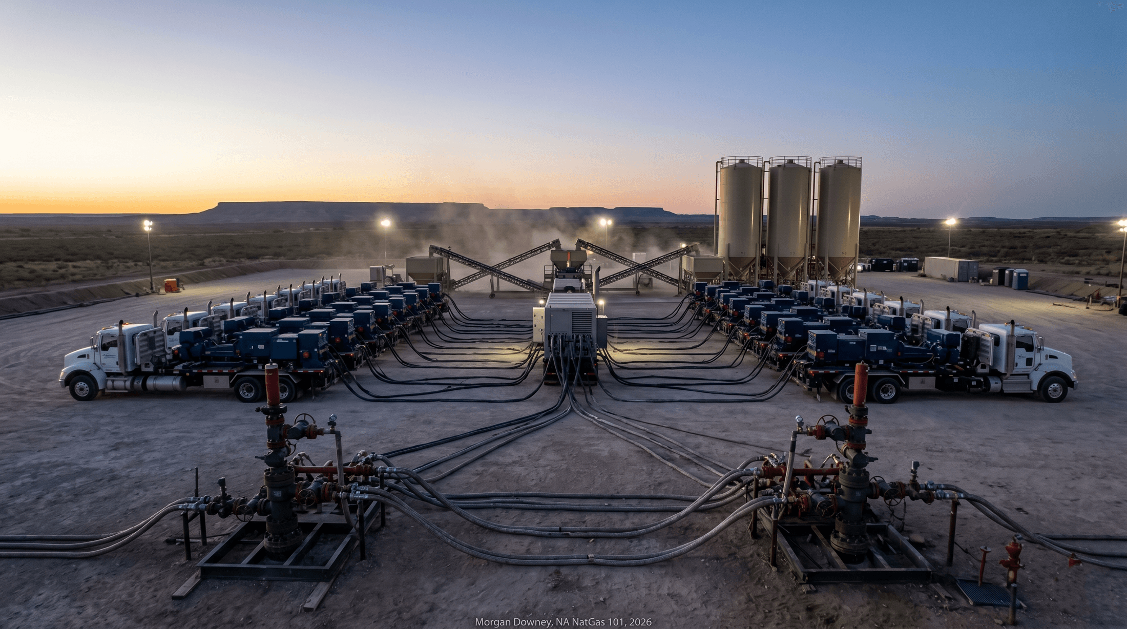
At 4 AM on a Weds August morning in 2024, a simul-frac spread on a Reeves County, Texas, pad consumed 1.5 million pounds of sand and 7,500 barrels of water before the day shift driller had finished his coffee. More than twenty electric-powered pump trucks fed two wells at the same time, alternating stages along laterals 11,500 feet long and a thousand feet apart at the surface, both landed in the Wolfcamp A bench at a true vertical depth of 9,400 feet.
Each pump truck pushed slickwater at roughly 80 barrels per minute into one of the two wells. Combined pump rate across the spread peaked above 160 barrels per minute. Sand silos rotated through five-minute loadout cycles to keep the blender full. A train of conveyor belts fed proppant from a mobile silo system that holds 12 million pounds across one pad, an inventory that turns over every four to six days at full pumping intensity.
The pad will produce roughly 25 thousand barrels of oil equivalent per day at peak from two wells, and most of that volume will arrive within the first six months of production. Without the frac, the wells produce nothing. Wolfcamp shale at 9,400 feet has matrix permeability measured in tens of nanodarcies. Gas and oil cannot flow to the wellbore through rock that tight; the artificial fracture network created during the completion is the entire reservoir-to-pipe pathway.
The first commercial application of this idea was a 1,000-gallon experimental treatment in 1947 on Stanolind Oil and Gas’s Klepper Well Number One in Grant County, Kansas. The pumped fluid was gasoline thickened with napalm. The proppant was river sand. The result was modest. The principle was the same.
What Hydraulic Fracturing Is
Hydraulic fracturing is the operation of pumping fluid down a wellbore at pressure high enough to break the surrounding rock, creating new fractures that propagate from the perforations into the formation, and leaving proppant behind to hold those fractures open after pressure is released. The principle is straightforward. The execution is industrial.
The pressure required to initiate a fracture is the formation breakdown pressure, which exceeds the minimum horizontal stress in the rock plus the rock’s tensile strength plus the friction lost as fluid flows through the perforations and into the near-wellbore region. Once a fracture is initiated, the pressure required to propagate it is the fracture extension pressure, which is lower than the initiation pressure because the rock at the fracture tip is already in tension. In a typical Marcellus or Haynesville completion, surface pumping pressures during the job run 8,000 to 11,000 psi. Bottomhole pressures at the perforations are higher than surface pressures by the hydrostatic weight of the fluid column, which in a 7,500-foot-deep Marcellus well adds roughly 3,500 psi to the surface pressure once the column is full.
Fractures grow in the direction of the maximum horizontal stress. The plane of a fracture is perpendicular to the minimum horizontal stress, because the rock parts most easily along the path of least resistance. In most US shale basins the maximum horizontal stress is oriented along a regional axis: roughly east-northeast in much of the Permian, north-northeast in much of the Marcellus, and northeast in much of the Eagle Ford. Operators orient laterals roughly perpendicular to the maximum horizontal stress so that fractures grow transverse to the wellbore, contacting more rock per stage than fractures that grow parallel to a wellbore drilled along the stress axis.
The reason the operation is necessary in shale and not in conventional reservoirs is permeability. Conventional sandstone and limestone reservoirs have permeabilities in the millidarcy range, often tens to hundreds of millidarcies, and gas and oil flow to a vertical wellbore through that rock without help. Shale source rocks have matrix permeabilities measured in nanodarcies, six orders of magnitude lower. A nanodarcy of permeability allows essentially no fluid flow through the matrix at the pressure differentials and timeframes a producing well sees. Without an artificial fracture network, shale produces almost nothing.
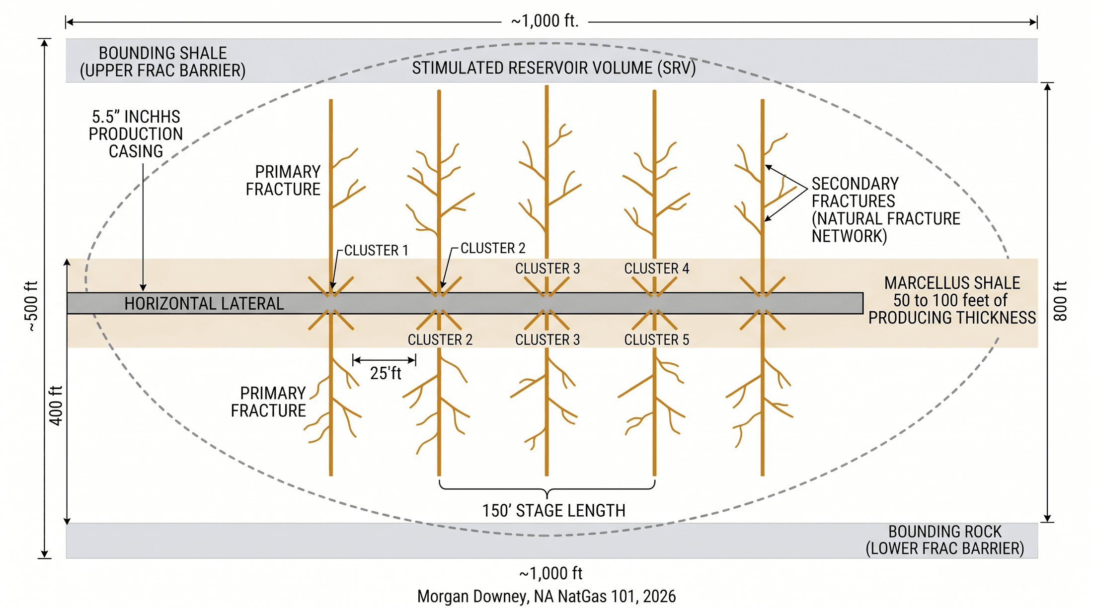
What fracking creates is not a single planar fracture but a stimulated reservoir volume. The pumped fluid generates a primary fracture along the maximum-stress direction, and secondary fractures branch off the primary along pre-existing weaknesses in the rock: bedding planes, natural fractures, and fault traces. The microseismic events recorded during the job map the perimeter of this volume. A typical modern shale stage stimulates a rock volume of roughly 200 to 600 feet on each side of the wellbore, with vertical extent constrained by the bounding formations above and below the producing zone.
Frac Fluid: Slickwater, Gel, Hybrid
Three families of fluid carry the proppant into the rock. They differ in viscosity, friction profile, cost per gallon, and the geometry of fracture they tend to create. The choice of fluid is the first structural decision in completion design.
Slickwater is the dominant fluid in modern US shale completions. The base is fresh or recycled produced water, treated to remove suspended solids and balanced for compatibility with the formation. The additives by volume are small. A friction reducer, typically a polyacrylamide polymer, is added at concentrations of roughly 0.5 to 1 gallon per thousand gallons of water, which cuts the friction pressure of water flowing through casing at 60 to 100 barrels per minute by roughly 70 to 80 percent. A biocide, typically glutaraldehyde or DBNPA, is added at low concentrations to prevent bacterial souring of the produced fluid. A scale inhibitor and a surfactant round out the mix. The total non-water content of slickwater is well under 1 percent by volume.
Crosslinked gel is a higher-viscosity fluid built around a guar polymer or guar derivative crosslinked with borate or zirconate to form a three-dimensional network. The gel carries proppant in suspension at pump rates as low as 20 barrels per minute, which matters in formations where high-rate pumping creates fracture geometry that loses proppant to upper or lower bounding zones. Gel was the dominant fluid in the conventional and tight-gas-sand era of the 1970s through 1990s, and it remains in use for tight-gas-sand completions in the Anadarko Basin Granite Wash, the Cotton Valley sand, and the deeper Pinedale anticline. The cost per gallon of crosslinked gel runs five to ten times the cost per gallon of slickwater, which alone makes it uneconomic at modern shale fluid volumes.
Hybrid fluids combine the two. A typical hybrid stage pumps slickwater for the first 30 to 50 percent of the stage volume to initiate complex fracture geometry and contact natural fracture networks, then transitions to a crosslinked gel for the proppant-carrying portion of the stage to push higher proppant concentrations deep into the fracture network without screen-out. Hybrid designs are common in the Bakken, the Eagle Ford liquids window, and parts of the Permian Wolfcamp where the formation responds to a complex frac geometry but the proppant intensity required exceeds what slickwater alone can carry.
The shift to slickwater was the single fluid decision that made shale economic. The Mitchell Energy team in the Barnett Shale tested slickwater treatments on the S.H. Griffin Estate wells in Wise County, Texas, in 1997 and 1998, and the wells outperformed equivalent gel completions on a cost-per-foot-of-EUR basis by enough that Mitchell rebuilt its standard Barnett completion around slickwater within two years. Every basin that came after, the Fayetteville, the Marcellus, the Haynesville, the Eagle Ford, and the Permian, adopted slickwater or a slickwater-based hybrid as the default fluid, and the gel-only conventional design was relegated to specific tight-gas-sand applications.
The composition of every frac job pumped on a US well is disclosed publicly. The FracFocus.org registry, jointly run by the Ground Water Protection Council and the Interstate Oil and Gas Compact Commission, holds chemical-disclosure forms for nearly every horizontal well drilled since 2011. Reporting is mandatory in most major producing states. Texas, Pennsylvania, Ohio, North Dakota, Colorado, and New Mexico all require submission either to FracFocus directly or to the state regulator with a parallel submission to FracFocus. Texas Railroad Commission Rule 29 specifies the disclosure framework for Texas wells.
Proppant: Sand, Ceramic, Resin-Coated
Proppant is the sand or engineered ceramic that the fluid carries into the fracture and leaves behind to hold the fracture open after the pump-down pressure is released. Without proppant, the fracture closes the moment the well is shut in, and the operator pumps eight million gallons of water for nothing. With proppant, the fracture stays open as a permeable channel back to the wellbore for the producing life of the well.
Three grades of proppant are in commercial use. Northern White Sand is high-purity silica sand mined from glacially deposited sandstone formations in Wisconsin, Minnesota, and Illinois. The grains are nearly pure quartz, well-rounded by glacial transport, and crush-resistant under closure stresses up to roughly 6,000 psi without losing significant conductivity. Northern White was the dominant proppant in US shale through 2016. Its weakness was logistics. Shipping it from the Upper Midwest to a Texas, Pennsylvania, or Louisiana wellsite cost as much as the sand itself, and rail-car backups at the source mines and at the destination terminals limited delivery rates during peak drilling activity.
In-basin sand displaced Northern White from most Permian completions starting in 2017. Sand mines opened near Kermit and Monahans in West Texas, on the dune sands of the Permian Basin floor, with capacity to supply the Delaware and Midland sub-basins by short-haul truck rather than long-haul rail. The Permian in-basin sand is lower-purity and less round than Northern White, with a measured crush strength of roughly 4,000 to 5,000 psi rather than 6,000 psi, but it is adequate for most Permian completions and saves $20 to $40 per ton on logistics. The Marcellus and Utica saw a parallel in-basin shift with sand mines opening in southwest Pennsylvania and West Virginia, though regional in-basin sand has not displaced Northern White as completely there as in the Permian.
Ceramic proppants are engineered grains made by sintering bauxite, kaolin, or lighter ceramic feedstocks. They are stronger, rounder, and denser than sand, with crush strengths of 10,000 to 15,000 psi, and they hold fracture conductivity at higher closure stresses than sand can. They are also four to ten times the cost per ton of in-basin sand. Their use is limited to the highest-pressure, highest-temperature plays where sand crushes and loses conductivity within months of completion: the deep Haynesville, the Bossier, parts of the deep Tuscaloosa Marine Shale, and select offshore applications. Resin-coated sand is a middle option, with a thermosetting resin coating applied to silica sand grains to bind them at depth, prevent flowback into the wellbore, and improve crush resistance over uncoated sand.
Mesh size, the diameter range of the proppant grains, varies with application. Common sizes in modern US shale completions are 40/70, 100, and 30/50, expressed in US sieve numbers. Smaller mesh, like 100, propagates deeper into narrow fractures and carries through high-pump-rate slickwater into distant parts of the stimulated reservoir volume. Larger mesh, like 30/50, is used where higher conductivity per fracture matters and the formation can take it. A modern Permian completion typically pumps a graded ramp, starting with 100 mesh in the early portion of each frac stage and stepping up to 40/70 as the pumping progresses, to balance reach and conductivity. The Haynesville at 11,500 feet of true vertical depth runs higher closure stresses than the shallower Permian and uses heavier 40/70 and 30/50 ramps with selective ceramic placement at the perforations.
Stage Design and Cluster Spacing
A modern shale completion is split into stages along the lateral, with each stage fractured as a discrete operation and isolated from previous stages by a composite plug or a sliding sleeve. Within each stage, the casing is perforated at multiple discrete points, called clusters, so that the pumped fluid enters the formation at several locations rather than a single point. Stage design, the length of each stage, the number of clusters per stage, and the spacing between clusters, controls how the fracture network develops and how much rock the completion contacts.
Stage length has shortened steadily across the industry. Early Marcellus completions in 2008 to 2012 ran stages 250 to 300 feet long, often with three to five clusters per stage. Modern Marcellus and Haynesville completions in late 2024 commonly run stages 130 to 200 feet long, with five to ten clusters per stage. Tighter stages mean more stages per lateral, which means more discrete pump-down events but also better stress distribution along the lateral and more uniform contact with the producing rock.
Cluster spacing is the distance between adjacent perforation clusters within a single stage. Early designs ran 50 to 80 feet between clusters. Modern designs commonly run 15 to 35 feet between clusters. The reason for tightening cluster spacing is that fractures from clusters closer together than the natural fracture-tip spacing of the formation interfere with each other, and the interference can either reduce per-cluster productivity or generate more complex fracture geometry that contacts more total rock. The empirical record across most basins through the 2010s suggested that tighter clusters delivered net positive contact, and operators converged on tighter spacing as a result.
Limited entry is the technique of designing the perforations within a stage so that flow distributes uniformly across all clusters during the frac. Without limited entry, fluid takes the path of least resistance and concentrates into one or two clusters, leaving the rest under-stimulated. Limited-entry design uses small perforation diameters, tight tolerances on perforation count per cluster, and specific pump-rate-to-perf-area ratios to force a calculated friction pressure across each perforation that exceeds the natural variation in formation breakdown pressure between clusters. Extreme limited entry, an evolution of the technique, uses very small perforation diameters (commonly 0.32 to 0.36 inch) and very tight perforation counts per cluster (commonly 3 to 6 perforations per cluster) to drive cluster efficiency above 90 percent in the best designs.
The total number of stages on a modern shale well scales with the lateral length and the chosen stage length. A 10,000-foot lateral with 175-foot stages contains 57 stages. A 12,000-foot lateral with 150-foot stages contains 80 stages. A 15,000-foot extended-reach lateral with 150-foot stages contains 100 stages. Stage counts above 100 are routine on the longest laterals in the Marcellus and Permian core acreage.
Stage design is not a single decision made once. Operators run experiments on test wells, called type-curve wells or science wells, to compare different stage lengths and cluster spacings on adjacent acreage and adjust their default design as data accumulates. The frac design that one operator runs as standard in 2024 differs from the design the same operator ran in 2018, and from what its competitor across the property line runs today. The convergence is slow because the experiments are expensive and the production data takes years to fully resolve. Parent-child fracture interference, where a new well’s frac communicates with a depleted older well drilled into the same bench, has emerged as a major design constraint since roughly 2018 in the Permian core, and operators routinely reduce proppant intensity on infill wells to limit the parent-well pressure response.
Plug and Perf, Sliding Sleeves, and the Completion Sequence
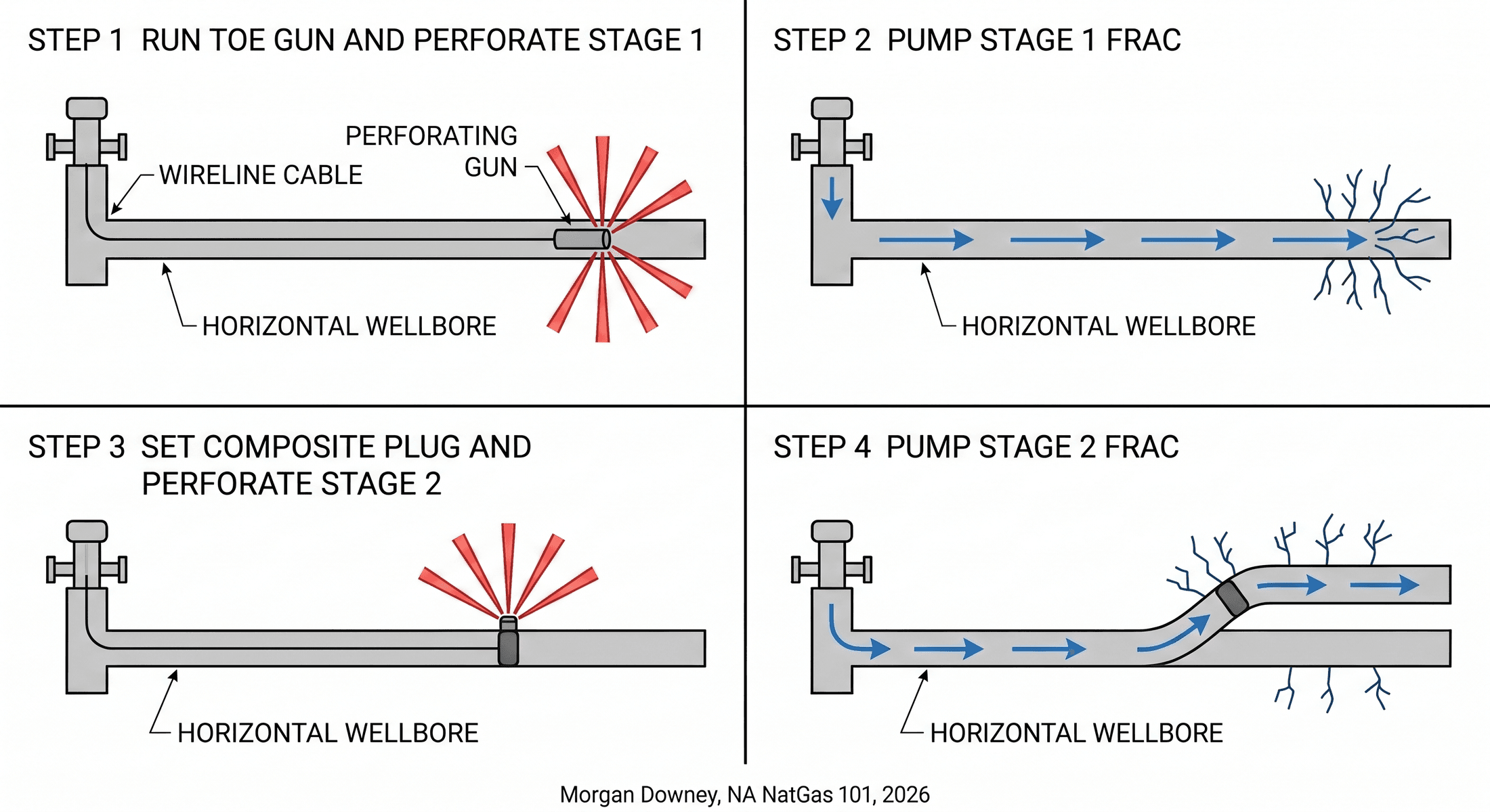
Plug and perf is the dominant completion method in modern US shale. After the lateral is drilled, cased, and cemented, a wireline crew runs a perforating gun to the toe of the lateral on electric line. The gun fires shaped charges through the production casing and the cement column into the formation, creating the perforations for the first stage. The wireline crew pulls the gun out of the well, the pumping spread starts the frac on stage one, and the fluid and proppant flow through the perforations into the rock.
After stage one is pumped, the wireline crew runs back into the well with a composite frac plug and a perforating gun on the same trip. The composite plug is set on the casing wall above the just-fracked stage, isolating it from the rest of the wellbore. Above the plug, the gun fires the perforations for stage two. The wireline trip pulls back to surface, the pumping spread fracs stage two, and the cycle repeats. A typical modern shale completion runs through 50 to 100 stages this way, with each stage taking roughly two to four hours from wireline-in to pump-down complete.
After all stages are pumped, the composite plugs are drilled out using coiled tubing or a workover rig, opening the full lateral to flow. Composite plug drillout typically takes one to three days. Once the plugs are drilled, the well is flowed back to recover the frac fluid, and the producing phase begins.
The advantages of plug and perf are precision and reliability. Each stage is isolated by a fresh plug, the perforations are placed at exactly the depths the design specifies, and the operator has the option to re-stimulate any stage by re-perforating between existing plugs. The disadvantage is wireline time. Each stage requires a wireline trip in and out of the well, and on a long lateral with many stages the wireline runs accumulate to a significant share of total completion time. Wireline truck day rates, perforating gun cost, and composite plug cost combined run roughly 8 to 15 percent of total completion cost on a modern shale well.
Sliding sleeves are the older alternative. A sliding sleeve completion runs a series of ported sleeves into the lateral, each one held closed by a removable seat sized for a specific ball diameter. To open stage one, the pumping spread drops the smallest ball, the ball seats on the toe sleeve, the pump pressure shears the seat retainer, and the sleeve slides open. The frac is pumped through the open sleeve. To open stage two, the next-larger ball is dropped, it seats on the second sleeve and bypasses the first, the second sleeve opens, and the frac continues. Each successive ball is larger than the last, so the system can run only as many stages as the casing diameter accommodates ball sizes.
Sliding sleeves were widely used in the early shale era because they did not require a wireline trip per stage. They have been displaced from the dominant position by plug and perf for several reasons. The maximum stage count was constrained by the ball-size ladder. Restimulation was difficult because the sleeves could not be reopened individually. And the ball seats sometimes failed to shear cleanly, leaving the wellbore in an ambiguous state mid-job. Modern shale completions run roughly 90 to 95 percent plug-and-perf and 5 to 10 percent sliding sleeve, with sleeves reserved for specific applications like open-hole gravel-pack completions and certain refrac jobs where wireline access through plugs is impractical.
Fluid and Proppant Volumes
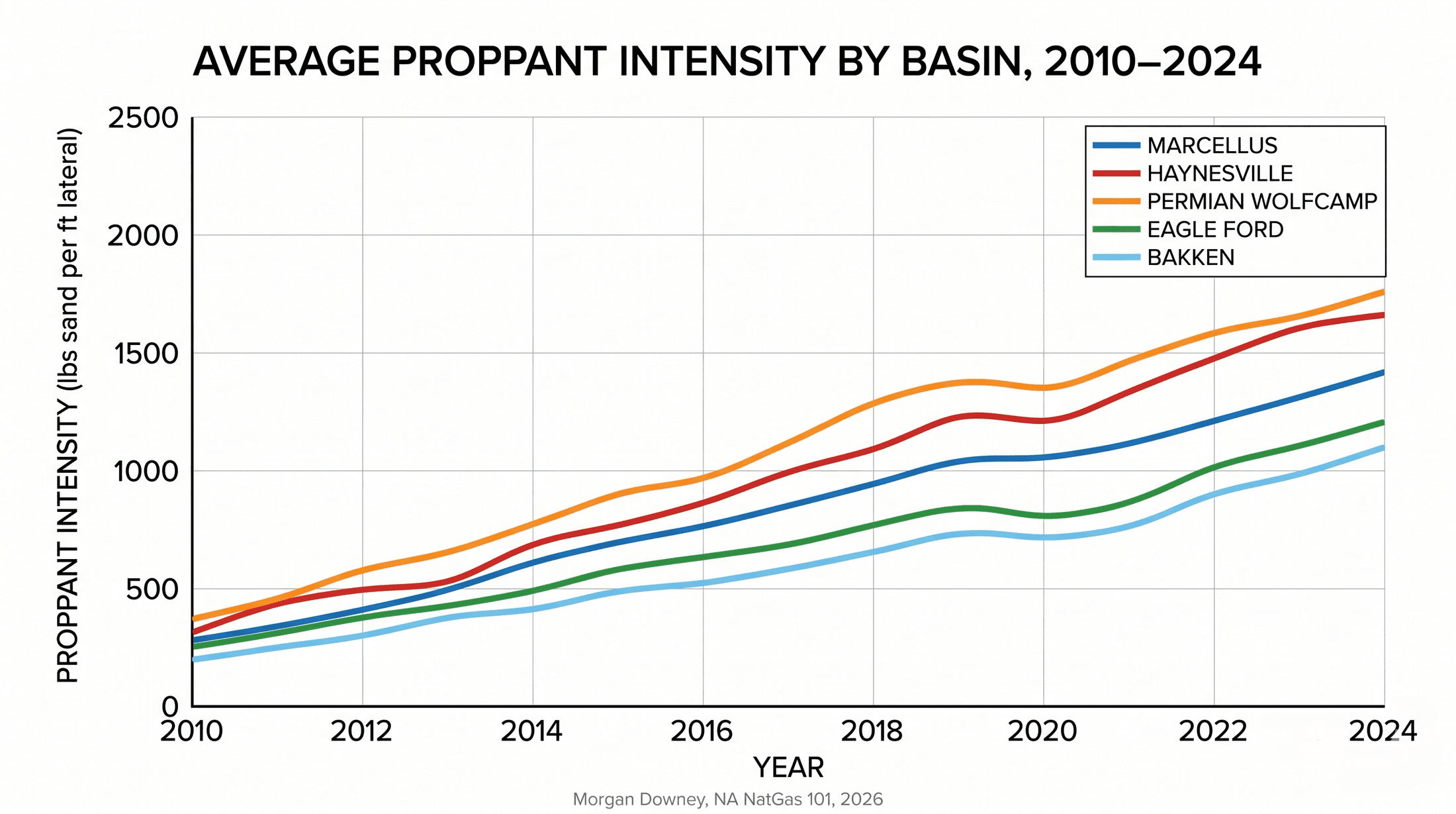
Per-well fluid and proppant volumes have grown roughly fivefold over the past fifteen years. The first Marcellus completions in 2008 to 2010 pumped 4 to 6 million gallons of slickwater and 2 to 4 million pounds of sand on 4,500-foot laterals. A modern Marcellus completion in late 2024 on a 12,000-foot lateral pumps 10 to 14 million gallons of slickwater and 10 to 16 million pounds of sand, with specific operators running 18 million pounds or more on their highest-intensity completions. Permian Wolfcamp completions on 10,000-foot laterals pump 18 to 25 million gallons of water and 20 to 30 million pounds of sand. Haynesville completions, on shorter laterals into deeper and hotter rock, run higher per-foot intensities still: 25 to 40 million pounds of sand on a 10,000-foot lateral is common in the dry-gas core.
The arithmetic of pump-time follows directly. A slickwater frac pumped at 80 barrels per minute moves 3,360 gallons per minute. A 12-million-gallon job pumped at that rate runs roughly 3,570 minutes, or 60 hours, of pumping spread across all stages. With wireline trips, plug-set time, and ramp-up between stages, the actual completion time on a single well runs 8 to 14 days, depending on stage count and operational intensity. On a multi-well pad with simul-frac or zipper-frac, the completion time per well is compressed because pumping continues on one well while wireline operations proceed on the adjacent well.
Sand handling at modern volumes is its own logistics problem. A 12-million-pound proppant load moves through the wellsite as roughly 250 truckloads, or 6,000 tons of sand staged in mobile silos at the pad and fed to the blender by conveyor. Modern silo systems hold 3 to 12 million pounds on-pad and reload from inbound trucks continuously while pumping is underway. Truck staging and unloading sequences are the operational bottleneck on most modern pads. Running out of sand mid-stage forces the spread to shut down, which costs more per hour than every other operational risk on a pad.
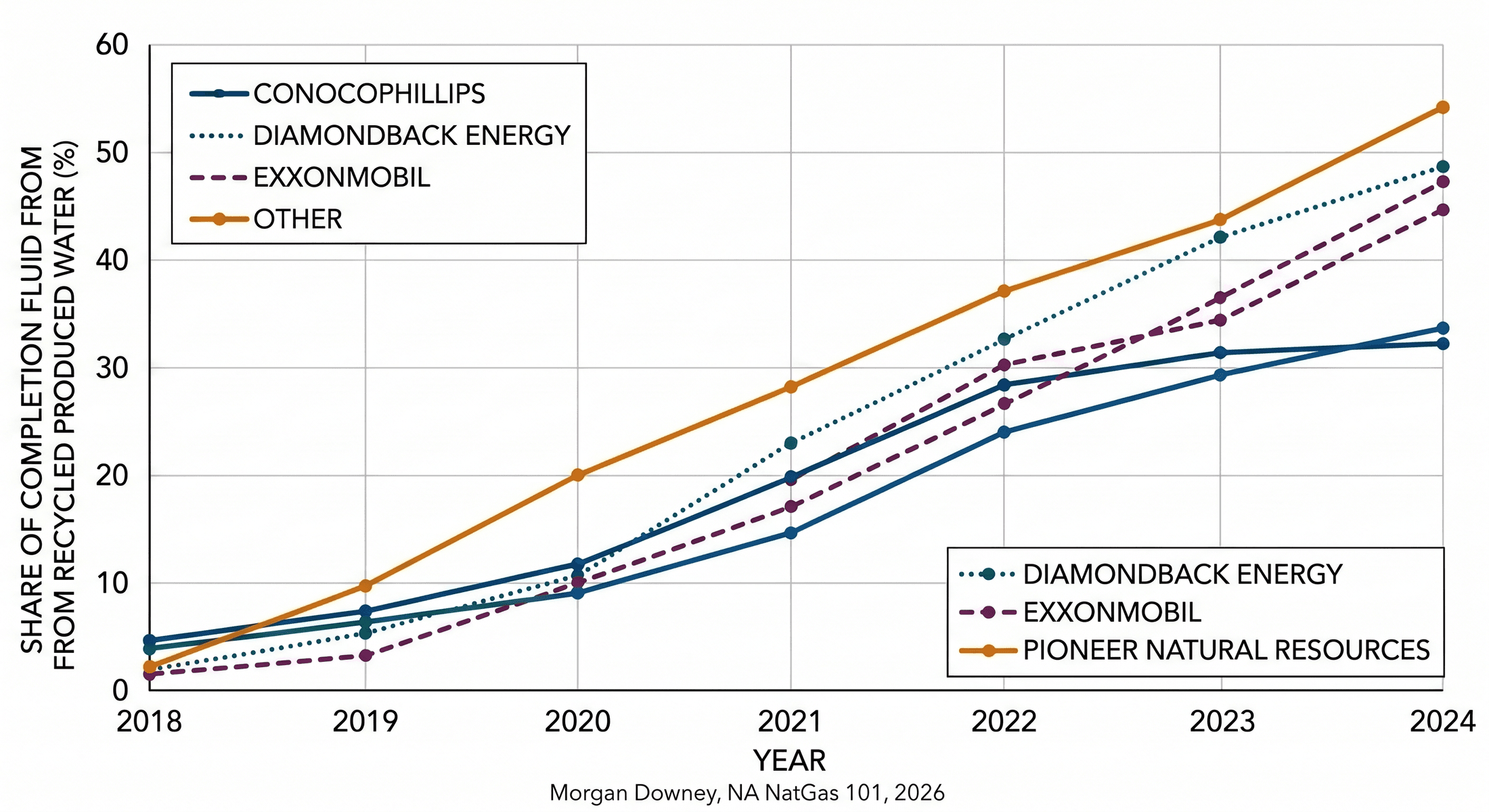
Water sourcing has shifted with completion-volume growth. Surface withdrawals from rivers and streams, regulated by state environmental agencies, supplied most early shale completions. The Susquehanna River Basin Commission permits Marcellus operators on a per-pad basis with monitored withdrawal rates, and the Delaware River Basin Commission has banned new shale drilling within its jurisdiction since February 2021. The Texas Railroad Commission and the Texas Water Development Board oversee Permian water sourcing, where surface water is scarce and operators rely on a combination of brackish-aquifer wells, municipal sources, and recycled produced water. Recycled produced water, the briny formation water that returns from previously completed wells, has grown from a marginal share of completion fluid in the early 2010s to a majority of completion fluid at some Permian operators by 2024. Reuse cuts both freshwater draw and the volume of produced water that has to be disposed of in saltwater injection wells, addressing two cost lines simultaneously.
Water Management and Disposal
Every barrel of water pumped into a frac comes back, sooner or later, mixed with the formation water that the well begins to produce as soon as it flows. Managing the return stream is the largest waste-handling problem in modern oil and gas operations.
Flowback is the fluid that returns up the wellbore in the first weeks after a frac is pumped. It is mostly the slickwater that went down, with progressively higher concentrations of formation salt, dissolved minerals, and entrained hydrocarbons as the days pass. Flowback volume runs roughly 10 to 40 percent of the original fluid pumped in a typical Marcellus or Permian completion, with the remainder either retained in the formation as imbibed water or returning later as produced water. Flowback rate is highest in the first 7 to 14 days and tapers steadily; by 90 days post-completion, the fluid coming up the wellbore is dominated by formation water rather than recovered slickwater.
Produced water is the briny formation water that flows continuously over the producing life of the well. The water-to-hydrocarbon ratio varies enormously by basin and by maturity stage of the field. The Permian Wolfcamp in late 2024 produces roughly 4 to 6 barrels of water for every barrel of oil at the field-wide level, with individual wells running higher and a small share running below 2 to 1. The Marcellus dry-gas core produces small amounts of water relative to gas, a few barrels of water per million cubic feet of gas at a typical Susquehanna County well, because the rock has minimal connate water and most of what returns is recovered slickwater. The Haynesville falls between the two, with moderate water rates that climb as the field matures.
Disposal moves the water back underground. Class II saltwater disposal wells (SWDs), regulated by the Environmental Protection Agency under the Underground Injection Control program and administered by state agencies in delegated states, inject the produced water into deep porous formations beneath the producing zone. In the Permian, the dominant disposal target is the Ellenburger Group, a Cambro-Ordovician dolomite at depths of 8,000 to 14,000 feet, which historically had high injectivity and low pressure relative to virgin conditions. In Oklahoma, the Arbuckle Group played the same role through the 2010s.
Induced seismicity changed the disposal picture. As cumulative volume of produced water injected into the Arbuckle climbed through the early 2010s, Oklahoma’s earthquake rate rose from roughly 2 magnitude-3-or-greater events per year before 2009 to more than 900 in 2015, with multiple events above magnitude 5, including the magnitude 5.8 event near Pawnee on Sat September 3, 2016. The Oklahoma Corporation Commission imposed volume caps on Arbuckle SWDs in seismic-sensitive areas in 2015 and tightened them through 2017. The Texas Railroad Commission established Seismic Response Areas in the Midland Basin in 2021 and 2022 and imposed shut-ins and step-downs on operators near elevated seismicity clusters. The New Mexico Oil Conservation Division followed with comparable rules in the Delaware sub-basin.
The combined effect of disposal-volume caps and produced-water economics has accelerated the shift to reuse. The share of completion fluid sourced from previously produced water rose from below 10 percent at most Permian operators in 2018 to above 50 percent at some operators by 2024. Treatment systems on-pad remove suspended solids, oil, iron, and bacteria from produced water and condition it to a quality that meets the friction-reducer chemistry requirements of slickwater. Beyond the wellsite, midstream water companies have built dedicated produced-water gathering systems with hundreds of miles of pipe across the Delaware Basin, replacing trucked-water logistics with continuous pipeline service.
Recent Trends: Longer Laterals, E-Frac, Simul-Frac
Three operational trends define the current state of US shale completions: longer laterals, electric fracturing, and simultaneous-pumping spreads. Each compounds the others.
Lateral length growth was treated in detail in Chapter 6. The completion implication is that a 15,000-foot lateral fracked at modern stage spacing carries 100-plus stages, requires proportionally more pumping time and proppant volume, and stresses the wellbore against friction limits that long-stroke pumping crews have to engineer around with reduced viscosity, higher friction-reducer loadings, and pump-pressure margins that did not need to exist on shorter wells. Some operators have run laterals of 18,000 feet or more on test acreage, including disclosed 4-mile laterals in the Marcellus core. Whether the practice generalizes depends on whether the marginal foot of lateral repays its additional completion cost.
Electric fracturing replaces the diesel engines that drove the previous generation of pump trucks with electric motors powered either by on-site natural gas turbines, by grid electricity, or by gas-engine generators that run on field gas piped from the producing wells. The first commercial e-frac fleet was deployed by US Well Services starting in 2014, and Halliburton, Liberty Energy, and ProPetro followed over the second half of the 2010s. Adoption accelerated rapidly after 2020 as operators looked for ways to reduce diesel fuel costs and emissions intensity simultaneously. By late 2024, electric, dual-fuel, and natural-gas-fueled spreads accounted for roughly 30 to 50 percent of active US frac capacity, with traditional diesel spreads still dominant but losing share each quarter. The economic case for e-frac runs on three lines: lower fuel cost when field gas is the energy source, lower routine emissions of NOx and methane, and longer pump-overhaul intervals on electric drives compared to diesel engines.
Simul-frac and trimul-frac spreads pump multiple wells from a single pumping operation. A simul-frac spread fracs two adjacent wells at the same time by alternating stages, with one well pumping while the other is wired up for the next stage. A trimul-frac extends the same logic to three wells, where pad geometry permits. The operational saving is days on-pad: a four-well pad that took 60 days to complete in sequence can be completed in 25 to 35 days simultaneously. The cost saving is per-well overhead on the pumping spread.
Zipper fracking is the older variant of the same idea. Pump one stage on well A while wireline preps the next stage on well B, then switch. Zipper fracking is universal on multi-well pads and has been since the early 2010s. Simul-frac is the more aggressive evolution, requiring a larger pumping spread but compressing on-pad time further.
The Barnett Shale, 1997
Mitchell Energy spent twenty years trying to make the Barnett Shale produce gas economically before it found the answer. Through the 1980s and into the mid-1990s, the company drilled vertical wells on its Newark East field acreage in Wise County, Texas, completed each one with crosslinked-gel fracs of 50,000 to 150,000 gallons, and watched almost every well decline within months to non-economic rates. The geology was right. The completion was wrong.
In 1997, Nicholas Steinsberger, an engineering manager at Mitchell, ran a slickwater experiment on an S.H. Griffin Estate well in Wise County. The job pumped roughly 1.2 million gallons of water with a small concentration of friction reducer rather than the gel-thickened fluid that had been Mitchell’s standard. The well outproduced its gel-completed neighbors by enough that Mitchell rebuilt its standard Barnett completion around slickwater within two years.
The cost difference was as important as the production gain. Slickwater at fifty cents per gallon plus minor additives, compared to crosslinked gel at six dollars per gallon, meant a Mitchell well that had been uneconomic at gel pricing was profitable at slickwater pricing on the same gas curve. Mitchell sold to Devon Energy in 2002 for $3.5 billion, and the Barnett became the proving ground that every shale play after it copied. The slickwater design that came out of Wise County was the completion template for the Fayetteville, the Marcellus, the Haynesville, the Eagle Ford, and the Permian.
The well is drilled, cased, fractured, and ready to flow. Chapter 8 turns to what comes back: production profiles, decline curves, and the economics of the producing life of a shale gas well.